Moore I/P kit for Moore 760E Positioner
We are no longer stocking this kit
Please contact AT controls
http://www.a-tcontrols.com/contact.html
We can provide the I/P only ABB Senycon Replacement I/P
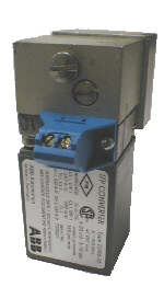
Series 760E Valve Controller I/P Converter Installation Kit
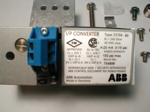
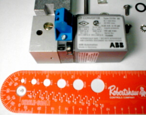 This is the Moore (now Siemens) kit for the 760E positioner,
Order P/N 15900-378. Note that these kits now have a different I/P in them.
INSTALLATION
The temperature in the intended operating location must not exceed the specified operating temperature limits of -40°C to +85°C. It is recommended to have a copy of the Service Instructions (SD760) available for easy reference.
See section 2.5 of SD760 for general and hazardous location wiring requirements. Control Drawing 15032-7602 is recommended for hazardous installations and is available upon request.
- Remove sealing plate screw and sealing plate. Retain the two "O"-rings.
- Install the two existing "O"-rings in their seats. Install 1/P manifold, new "O"-rings, and I/P provided with the kit. Secure in place with new screw.
-
Attach the input leads (recommend 22 AWG shielded, twisted pair wire minimum) to the + and connections of the I/P converter terminal strip. The wire should enter the controller through the conduit connection and be routed through the wire clamp (refer to Figure 1).
- Attach the wire clamp with its screw.
- Install pipe plug in input port. Install ground screw and washer. Install clamping plate with toothed lockwasher and screw
Calibration
It is not necessary to calibrate the I/P transducer; however, calibration adjustments are available. The I/P transducer can be adjusted by following the procedure outlined below. The I/P accepts a 4-20 mA signal.
Verify the output of the I/P converter as follows:
- Connect a 0-30 psi test gauge to the 1/8 in. NPT input gauge port.
- Apply supply pressure to the supply connection.
- Apply a 4 mA input signal. Any deviation in the output signal from 3 psi can be corrected with the zero adjustment screw ( >0< ).
- Increase the input signal to 20 mA. Any deviation in the output signal from 15 psi can be corrected with the range potentiometer (<|-|>).
- If necessary, perform the valve controller zero and span functions as described in Section 4.0 (Calibration) of SD760.